
- Home
- Products
- About Us
- Download
- News
- Blog
- Contact Us
Leave Your Message
Substations rely on switching equipment to control power flow, isolate faults, and protect workers during maintenance. The phrase “Substation Switchs” is often used broadly, but switch designs differ in purpose, voltage range, and operating method. Some devices interrupt load current; others provide visible isolation only. That difference matters. Choosing the wrong type can compromise safe operation or complicate maintenance.
This guide introduces ten common types of substation switches, including disconnectors, circuit breakers, load-break switches, earthing switches, and fuse switches. It also considers transfer, bypass, and air-break arrangements, along with equipment used in gas-insulated substations. Not every industry classifies these devices in exactly the same way. Names and configurations can vary by manufacturer and application, so the list is a practical overview rather than a universal ranking.
The distinctions become clearer in real equipment. A disconnector may create a visible open gap, while a circuit breaker is designed to interrupt fault current. An earthing switch connects isolated equipment to ground for maintenance procedures. Even familiar labels can be misleading. Ratings, interlocks, insulation levels, and site conditions all affect whether a device is suitable. The following overview explains what each type does, where it is commonly used, and which selection details deserve closer attention. It cannot replace a qualified engineering review, but it can help readers ask better questions when comparing substation designs.
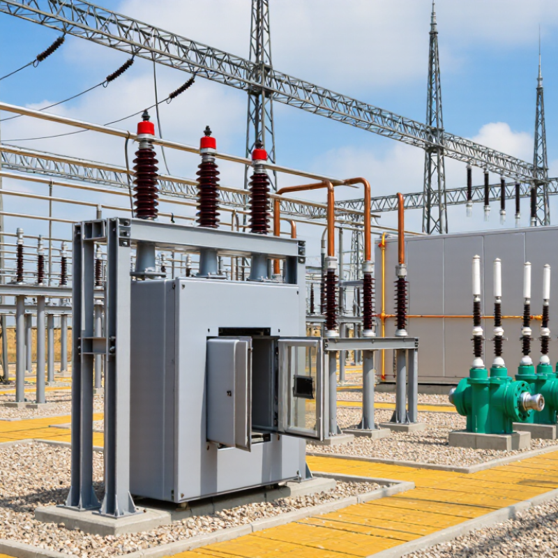
What Are the Top 10 Types of Substation Switches?
Substation switches control, isolate, and ground parts of an electrical network. Their jobs differ. A circuit breaker interrupts fault current, often after a protective relay detects abnormal conditions. A load-break switch handles normal load current, while a disconnector creates an isolation gap after current has been interrupted. Never treat them as interchangeable.
Common types include circuit breakers, air-break disconnectors, center-break disconnectors, pantograph disconnectors, earthing switches, load-break switches, bus-section switches, bus-coupler switches, bypass switches, and fuse switches. Operators may use a motor or stored spring energy to move contacts; interlocks help prevent unsafe sequences. An earthing switch grounds isolated equipment so induced or trapped charge has a safe path away. Small details matter: contact alignment, visible separation, and the sound of a mechanism can all reveal a problem. A diagram looks neat. A real yard is less forgiving.
The U.S. Department of Energy’s 2023 National Transmission Needs Study projects that U.S. transmission capacity needs could grow two to five times by 2050, depending on scenario and region. More network capacity makes dependable switching and maintenance isolation increasingly important. IEC 62271-102 also specifies requirements for high-voltage disconnectors and earthing switches. Still, standards cannot replace site-specific procedures. Even experienced teams should verify equipment labels and switching conditions before operation.
| Type | What It Does | How It Works | Can It Interrupt Load or Fault Current? | Typical Substation Use |
|---|---|---|---|---|
| 1. Power circuit breaker | Switches circuits on and off and clears overloads or short circuits when commanded by protection systems. | Separating contacts create an arc; an interrupting medium—such as vacuum, gas, or air—extinguishes it. | Yes. Designed to interrupt normal load current and specified fault current. | Transformer bays, feeder bays, bus sections, and transmission lines; used across distribution and transmission voltage classes. |
| 2. Disconnect switch (isolator) | Provides visible or otherwise verifiable isolation for equipment during maintenance. | Moving contacts open to create an isolation gap after the circuit has been de-energized or current has been interrupted elsewhere. | Generally no. It is not intended to break load or fault current. | Installed around breakers, transformers, and line connections; operating procedures interlock it with associated breakers. |
| 3. Grounding (earthing) switch | Connects isolated conductors to earth to help protect workers and discharge induced or trapped charge. | A blade or contact closes onto a grounded terminal, bonding the isolated circuit to the substation earth grid. | Normally no. Some designs are rated to close onto a specified fault current; this does not make them general-purpose breakers. | Used on line, bus, or equipment sides of isolators, subject to approved safety procedures. |
| 4. Load-break switch | Makes and breaks normal operating current, commonly in medium-voltage networks. | Contacts and an arc-control system—often vacuum or gas-based—interrupt the specified load current. | Yes for rated load current; typically not for high short-circuit current unless paired with protective equipment. | Medium-voltage feeder switching, transformer switching, and ring-main arrangements. |
| 5. Fused load-break switch | Combines load switching with fuse-based protection, often for transformer circuits. | The switch handles normal load switching; a fuse melts to clear specified overcurrents and may trigger the switch to open all phases. | Switch: rated load current. Fuses: interrupt fault current within their published ratings. | Common in medium-voltage transformer protection where the equipment design and coordination study permit its use. |
| 6. Transfer or bypass switch | Transfers a circuit between alternative sources or routes, or provides a bypass path around equipment. | Interlocked switching devices change the circuit connection in a defined sequence; some designs allow open-transition operation, while others support closed transition when specifically engineered. | Depends on design. The switching device must be rated for the current and switching duty involved. | Used for supply transfer, maintenance bypasses, and selected bus or auxiliary-supply arrangements. |
| 7. Bus-section switch | Connects or separates sections of a substation bus to support operating flexibility and maintenance. | A switching device opens or closes the connection between bus sections; the device may be a circuit breaker or, where permitted, a switch-disconnector. | Depends on the installed device. A breaker can clear fault current; a disconnector generally cannot interrupt load current. | Used in sectionalized bus layouts to isolate a bus section or limit the extent of an outage. |
| 8. Bus-coupler breaker | Connects two busbars and allows controlled transfer or sharing of supply between them. | A circuit breaker closes the bus connection and opens it on an operator command or protection-system trip. | Yes, within its rated load and fault-interruption capabilities. | Used in double-bus and sectionalized-bus substations; the bus-coupler breaker is a breaker application, not a separate interruption technology. |
| 9. GIS three-position switch | Provides a compact combination of circuit connection, isolation, and earthing functions in gas-insulated switchgear. | A movable contact selects one of three positions: connected, isolated, or earthed. A separate circuit breaker normally performs fault interruption. | Typically not for fault current; switching capability depends on the specific switch design and rating. | Compact GIS bays in indoor or space-constrained substations, commonly at medium and high voltages. |
| 10. High-speed grounding switch | Rapidly grounds a conductor in specialized arrangements, including selected protection schemes. | A fast-acting mechanism closes a grounding contact; its operating sequence and duty are coordinated with the associated protection system. | Some models can close onto specified fault current, but they are not substitutes for circuit breakers. | Used in particular GIS or transmission applications; use is design- and protection-scheme-specific. |
Note: Ratings and permitted duties vary by equipment design, voltage class, applicable standards, and operating procedure. Always consult the equipment nameplate and approved switching instructions.




 Send Email
 Phone
 whatsapp
 Wechat
 Whatsapp
