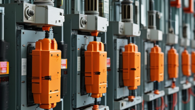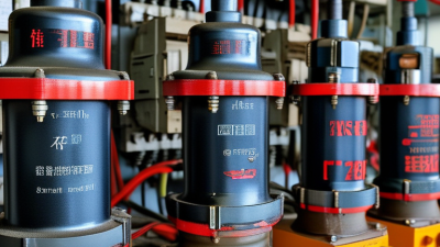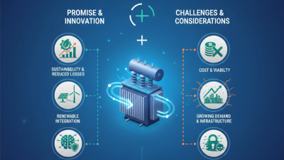
Why Choose Fuse Cutouts for Electrical Protection? The question matters as distribution networks become more exposed to rising demand, weather, and equipment failure. NERC’s 2024 Long-Term Reliability Assessment projects North American peak demand to increase by approximately 15% over the next decade. More load means greater pressure on transformers, feeders, and overhead lines. Protection must respond quickly.
Fuse Cutouts offer a practical solution for many medium-voltage distribution systems. They combine switching visibility with current-limiting fuse protection. During a fault, the fuse element melts and interrupts abnormal current before damage spreads. The cutout then provides a visible operating position for inspection crews. That detail matters in the field. A technician can see whether the device has operated from ground level, depending on the installation.
Industry standards support careful application. IEC 60282-2 addresses expulsion fuses and their use in high-voltage systems. IEEE Std 1366 provides common reliability measures, including SAIDI and SAIFI, helping utilities evaluate outage performance. NERC reports also emphasize stronger planning for extreme weather and changing load patterns. Fuse Cutouts cannot solve every reliability problem. They may require coordination studies, correct fuse sizing, and regular inspection. A poorly selected fuse can create nuisance operations or delayed fault clearing.
That limitation deserves attention. Simple equipment is not automatically simple to engineer. Yet, when properly specified, installed, and maintained, Fuse Cutouts can provide economical protection, clear fault indication, and dependable isolation across overhead distribution networks.
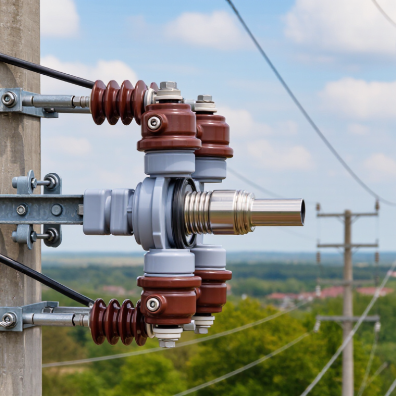
Fuse cutouts are outdoor protection devices used on overhead electrical distribution lines. They combine a fuse link, a carrier, and an insulating support. Under normal conditions, current passes through the fuse link. If a short circuit or overload occurs, heat melts the link and opens the circuit.
Many fuse cutouts use an expulsion action. As the fuse operates, the carrier drops away and helps interrupt the arc. This creates a visible disconnection for trained electrical workers. The open position also makes faulted equipment easier to identify during inspection. However, performance depends on correct voltage, current, interrupting, and coordination ratings. A poorly selected fuse may operate too early or fail to protect downstream equipment.
Tips: Inspect the porcelain, contacts, hinge, and fuse tube for cracks, corrosion, or looseness. Check that the fuse rating matches the transformer and system design. Keep vegetation and debris away from the device. Do not operate a damaged cutout. Field experience shows that small contact problems can create heat before a fuse responds. That detail is easy to overlook.
Fuse cutouts are practical because they provide both automatic fault protection and a clear visual indication. They are not flawless. Wind, moisture, contamination, and aging can reduce reliability. Installation and replacement should follow approved procedures, local electrical rules, and the equipment manufacturer’s technical data.

Fuse cutouts protect overhead distribution lines with a simple, visible mechanism. Their main parts include a fuse link, fuse tube, contacts, porcelain or polymer insulators, and a mounting frame. The link carries normal current. Excess current heats its element until it melts. The tube then separates and helps extinguish the arc. The cutout usually drops open, giving technicians a clear visual indication of a fault.
The tube matters. Its internal lining can release gas during arcing, cooling and lengthening the electrical path. Spring-loaded contacts improve pressure and reduce unwanted heating. Insulators maintain clearance from the supporting structure, even during rain, dust, or salt exposure. IEEE Std C37.41 defines test requirements for distribution-class fuse equipment, including interruption and temperature performance. In field inspections, loose hardware often deserves as much attention as the fuse rating.
U.S. Energy Information Administration data for 2018–2022 placed average transmission and distribution losses near 5% of electricity supplied. A fuse cutout cannot remove those system losses, but it can limit fault damage and prevent wider outages. Correct coordination remains essential. The fuse must operate before downstream equipment suffers thermal stress, while avoiding unnecessary operation during temporary faults. That balance is imperfect. Engineers should verify available fault current, load growth, ambient temperature, and fuse curves together. A visual inspection should also check corrosion, cracked insulation, bird contamination, and signs of arcing. Small parts matter.
Key components and the operating principle of a fuse cutout
A fuse cutout combines a fuse link, upper and lower contacts, a hinged carrier, and an expulsion tube. When fault current rises, heat generated in the fuse element increases according to the electrical relationship P = I²R. The fuse link melts, while the expulsion tube helps interrupt the arc and the carrier drops open to provide visible isolation.
The chart shows relative heating energy when resistance and operating time remain constant. Doubling the current produces four times the heating energy, which explains why fuse cutouts can respond rapidly to high-current faults and help protect distribution transformers and overhead circuits.
Relative heating values are calculated from I²R using current multiples of the rated current; actual clearing time depends on fuse-link design, ambient conditions, fault current, and system voltage.
Fuse cutouts improve electrical system protection by interrupting fault currents near transformers and overhead feeders. When correctly rated, the fuse link melts quickly during overloads or short circuits. The cutout then drops open, creating a visible isolation point for maintenance crews. That physical gap matters on a wet pole, beside a humming transformer, or after a storm. It reduces equipment damage and supports safer fault identification.
Industry data shows why this protection deserves attention. The U.S. Energy Information Administration reported about 5.5 hours of average customer interruptions in 2022, including major events. IEEE Standard 1366 provides the accepted framework for measuring these interruptions. A properly coordinated fuse cutout can limit the affected section instead of disconnecting an entire feeder. However, installation quality remains critical. Wrong fuse ratings can cause nuisance operations or delayed clearing. That mistake is easy to overlook.
NFPA 70B emphasizes documented electrical maintenance and inspection. Field teams should check contacts, hardware, corrosion, and fuse condition during scheduled work. A damaged hinge may prevent reliable operation when the system is under stress. Fuse cutouts are not a complete protection strategy. They should work with grounding, surge protection, sectionalizing devices, and tested coordination studies. Real systems are rarely perfect. Dust, salt, wildlife, and aging connections still create uncertainty. For that reason, maintenance records and post-fault inspections should guide replacement decisions, not appearance alone.
| Protection Dimension | How Fuse Cutouts Work | Protection Benefit | Typical Practical Data |
|---|---|---|---|
| Overcurrent Protection | A fusible link melts when current remains above its time-current operating characteristic, opening the circuit. | Protects distribution transformers, conductors, and connected equipment from sustained overloads and short-circuit currents. | Single-phase Commonly used on overhead distribution transformer primary circuits. |
| Short-Circuit Interruption | The fuse element operates during a fault, while the cutout body helps extinguish the arc as the circuit opens. | Limits the duration of fault current and reduces thermal and mechanical stress on electrical equipment. | Interrupting ratings are application-specific and must be selected from the equipment nameplate and applicable standard. |
| Voltage Compatibility | The cutout is selected for the system voltage and insulation requirements of the overhead network. | Provides adequate insulation and safe interruption under the intended operating conditions. | Common distribution classes include 15 kV, 25 kV, and 35 kV systems; exact ratings vary by design. |
| Current Rating | The fuse link is chosen according to transformer load current, conductor capacity, inrush current, and coordination requirements. | Helps prevent nuisance operations while maintaining protection against damaging overcurrent conditions. | Fuse-link ratings are commonly available from a few amperes to several hundred amperes, depending on the cutout design. |
| Transformer Protection | The primary fuse link disconnects a transformer when an internal or downstream fault produces excessive current. | Reduces the risk of transformer damage, fire, and extended service interruption. | Selection should consider transformer full-load current, magnetizing inrush, secondary protection, and available fault current. |
| Visible Circuit Status | After operation, the fuse carrier typically drops or moves to provide a visible indication that the fuse has opened. | Allows field personnel to identify an operated protective device before troubleshooting or replacement. | Visual indication is useful on pole-mounted equipment, but the circuit must still be tested and properly isolated before work. |
| Isolation and Maintenance | The removable fuse carrier can be manually withdrawn using approved live-line tools when permitted by operating procedures. | Supports maintenance access and fault investigation without installing a separate visible disconnect at every protected point. | Live-line operation depends on local rules, worker qualification, weather conditions, and the equipment rating. |
| Time-Current Coordination | Fuse links are selected using their time-current curves in relation to upstream and downstream protective devices. | Improves selective operation so that the smallest practical section of the network is disconnected during a fault. | Coordination should account for minimum melting time, total clearing time, transformer inrush, and downstream device curves. |
| Current-Limiting Capability | Standard expulsion fuse cutouts interrupt fault current by expelling gases and are not automatically current-limiting fuses. | Provides reliable fault interruption within the device rating, while avoiding incorrect assumptions about peak-current limitation. | Use a separately rated current-limiting fuse when peak let-through current reduction is required by the system study. |
| Outdoor Environmental Use | Porcelain or polymer insulation separates energized parts from the grounded support structure in outdoor installations. | Supports operation in exposed overhead environments when correctly rated and maintained. | Performance depends on creepage distance, pollution level, altitude, moisture, ultraviolet exposure, and hardware condition. |
| Operational Simplicity | The device combines a fuse link, carrier, insulator, and mounting hardware in a compact outdoor assembly. | Reduces installation complexity and makes routine inspection and fuse replacement comparatively straightforward. | Replacement requires the correct fuse-link type, rating, and installation torque according to the equipment instructions. |
| Cost and Lifecycle Considerations | The basic construction uses relatively few components and does not require a control power supply for operation. | Offers a practical protection solution for many overhead feeder and transformer applications. | Lifecycle cost includes inspection, spare fuse links, truck access, outage time, and periodic hardware replacement. |
| Safety Requirements | The fuse cutout is one part of a complete protection and isolation system, not a substitute for safe work practices. | Proper grounding, switching procedures, arc-flash assessment, and absence-of-voltage testing reduce personnel risk. | Always follow the applicable electrical safety standard, utility procedure, and manufacturer operating instructions. |
Fuse cutouts provide a visible and dependable way to protect distribution equipment. Their design separates a faulted circuit from energized lines. This action can protect transformers, conductors, and nearby equipment from severe damage. They are also practical for outdoor networks, where maintenance crews need clear visual confirmation.
Dropout fuse cutouts are widely used on overhead distribution poles. When the fuse operates, the holder swings open and creates an obvious isolation point. Expulsion fuse cutouts use gases produced during fault interruption. They suit many medium-voltage feeder and transformer applications. Current-limiting fuse cutouts reduce fault energy quickly and can protect sensitive equipment in compact substations. Some systems use solid fuse designs where silent operation and enclosed protection matter more.
Selection is not always obvious. A neat installation can still be poorly matched. Engineers should check system voltage, continuous current, interrupting capacity, insulation level, and available fault current. The fuse curve must coordinate with upstream and downstream protective devices. Otherwise, a small fault may disconnect an unnecessarily large section of the network. Field inspections should also examine corrosion, cracked insulators, loose connections, and signs of overheating.
Tips: Confirm ratings from current engineering documents. Keep the fuse type consistent with the cutout body. Inspect contact pressure and alignment during scheduled maintenance. Do not rely only on visual condition; hidden heating can develop inside connections. When conditions change, such as added transformer capacity, protection settings should be reviewed again.
Fuse cutouts provide visible, dependable protection for overhead distribution equipment. They interrupt fault current and isolate damaged sections from the network. Selection starts with system voltage, continuous current, fault level, and insulation requirements. The fuse link must match the protected transformer or feeder. Check time-current curves and coordination with upstream devices. A higher rating is not always safer. It may delay fault clearing.
Installation requires trained electrical personnel and a verified de-energized circuit. Inspect the cutout, fuse link, contacts, and mounting hardware before work begins. Confirm phase spacing, grounding, and operating clearance. Tighten connections to the manufacturer’s specified torque. A loose terminal can create heat, noise, and eventual failure. After installation, test mechanical operation and inspect the completed assembly. Small details matter.
Tips: Keep spare fuse links dry and correctly rated. Never bypass a fuse with wire or an unsuitable link. During maintenance, look for cracked porcelain, corrosion, discoloration, and damaged hinges. Thermal scanning can reveal hot connections before visible damage appears. Replace suspect parts promptly. However, maintenance plans should reflect local conditions. Coastal salt, dust, wildlife, and repeated switching can change inspection intervals. A standard schedule may be a useful starting point, but field evidence should guide revisions.